14.4 Terabits in a single rack unit ?

Have switching ASICs gotten too fast?

Looking back at the last few years it certainly appears that ethernet switching ASICs and front panel interface bandwidth are clearly moving at a different pace in that a faster switching ASIC comes just ahead of the required ethernet interface speed and optic form factor size required to drive the full bandwidth the ASIC actually provides while still fitting into a 1RU top-of-rack ethernet switch or line card profile.

Current 6.4+ Tbps system on-a-chip (SOC) ASIC based switching solutions have moved past the available front panel interface bandwith inside of a single rack unit (RU).  The QSFP28 (Quad-SFP) form factor currently occupies the entire front panel real estate of a 1RU switch at 32x100G QSFP28 ports prompting switching vendors to release 2RU platforms in order to cram 64x100G ports and fully drive the newest switching ASICs. With higher bandwidth switching ASICs on the near horizon the industry clearly needs a higher ethernet interface speed and new form factors to address the physical real estate restrictions.

So where do we go from here?

First lets look at the 3 available dimensions at our disposal for scaling up the interface bandwidth.

1.)  Increase the symbol rate per lane.

This means we need an advance in the actual optical component and thermal management used to deliver the needed increase in bandwidth in a power efficient manner.  Put more simply in the words of a ceratin  Evil Scientist who wakes up after being frozen for 30 years “I’m going to need a better laser okay”.

2.)  Increase the number of parallel lanes that the optical interface supports

As an example in the case of the 40Gbps QSFP form factor this meant running 4 parallel lanes of 10Gbps to achieve 40Gbps of bandwidth

3.)  Stuff (encode) more bits into each symbol per lane by using a different modulation scheme.

For example PAM4 encodes 2 bits per signal which effectively doubles the bit rate per lane and is the basis for delivering 50Gbps per lane and 200Gbps aggregate across 4 lanes.

Looking Beyond QSFP28

Next looks look at what is potentially coming down the pike for better interface bandwidth (greater than 100Gbps) and front panel port density.

Smaller form factor 100G

One approach is to simply used a more compact form factor and this is exactly what the micro QSFP is being designed to do.  uQSFP is the same width as an SFP form factor optic yet uses the same 4 lane design of QSFP28. This translates into a 33% increase in the front panel density of a 1RU switch when compared with the existing QSFP28 form factor. The uQSFP also draws the same 3.5W of power as the larger form factor QSFP28.  Its now going to be possible to fit up to 72 ports of uQSFP (72x100G) into a 1RU platform or line card allowing for the support of switching ASICs operating at 7.2Tbps when the uQSFP runs at 25Gbps per channel (4 lanes of 25Gbps).  If broken out into 4x25G ports a single 1RU could terminate up to 288 x 25G ports.  uQSFP is also expected to support PAM4 enabling 50Gbps per channel for an effective bandwidth of 200Gbps in a single port paving the way for enough front panel bandwidth to drive 14+Tbps of switching ASIC capacity in a 1RU switching device form factor.  There may however be technical challenges in engineering a product with 3 rows of optics on the front panel.

Image courtesy of http://www.microqsfp.com/

Double-Density Form Factors

Another approach is the QSFP-DD (double density) form factor.

QSFP28-DD is the same height and width of QSFP28, but slightly longer allowing for a second row of electrical contacts.  This second row provides for 8 signal lanes operating at 25Gbps for a total of 200Gbps in the same amount of space as the previous QSFP28 operating at 100Gbps.  This provides enough interface bandwidth and front panel density for 36 x 200Gbps and a 7.2Tbps switching ASIC.  There are break-out solutions coming that will allow for breaking out into 2x100Gbps QSFP28 connections with QSFP-DD optics on the 100G end.   What is not yet clear is whether a product will emerge which would allow for 8x25G breakouts of a QSFP28-DD into server cabinets.

400G

CFP8 is going to be the first new form factor to arrive for achieving 400G, but is going to be too large a form factor to fit into the more traditional model of 32 front panel ports in 1RU of space.  CFP8 dimensions are W 40 x L 102 x H 9.5 which should max out at around 18 ports per 1RU of space.  At 15-18W (3x the power of QSFP28), power consumption is another challenge in designing a line card that can accomodate it.  CFP8 is more likely to be used by service providers for router to router and router to transport longer haul transmissions rather than traditional ethernet switching devices found in the Data Center rack.

QSFP56-DD consists of 8 lanes of 50Gbps with PAM4 modulation for 400Gbps operation.  Its the same size form factor as QSFP/QSFP28 allowing for up to 36 ports in 1RU of space and flexible product designs where QSFP, QSFP28 or QSFP56-DD modules could alternatively be used in the same port.  These 36 ports of 400Gbps would support ASICs with 14.4Tbps in a single RU of space.  QSFP56-DD should also support short reach 4x100Gbps breakout into 4x SFP-DD which is the same size as SFP+/SFP28 making it eventually ideal for server connectivity.

Octal SFP (OSFP) is another new form factor with 8 lanes of 50Gbps for an effective bandwidth of 400G.  Its slightly wider than QSFP, but should still be capable of supporting up to 32 ports of 400G, a total of 12.8Tbps in 1RU of front panel space.  The challenge for OSFP adoption will be that its a completely different size form factor than the previous QSFP/QSFP28 which will require a completely new design for 1RU switches and line cards.  In other words there will be no backwards compatability where a QSFP/QSFP28 could be alternatively be plugged into the same port on line card or fixed switch. An adapter for allowing a QSFP28 optic to be inserted into the OSFP form factor is apparently under discussion.

So in conclusion just while ASICs seemed to be quickly outpacing interface bandwidth and front panel real estate there are viable options coming soon that will be able to take us to the 12.8 to 14.4Tbps level in a single RU.

Disclaimer: The views expressed here are my own and do not necessarily reflect the views of my employer Juniper Networks

Understanding optics and cabling choices in the Data Center

Do you find the dizzying array of optics form factors, connector types, cabling choices and device connectivity options in the Data Center difficult to consume and make sense of?  In this particular segment we will look at some of the most popular types of Data Center optics and cabling options out there as well as examples of commerically available switching product platforms that leverage these. We will then cover the factors that influence when one might choose a specific type of optic and cabling for connecting end devices to these switches and wrap up with a table which summarizes what we have discussed.

When it comes to optics some important concepts to quickly knock off right out the gate are form factor, transceiver, connector type and cabling.

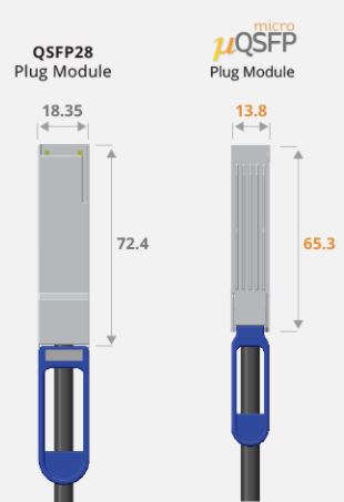
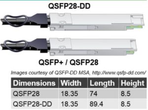
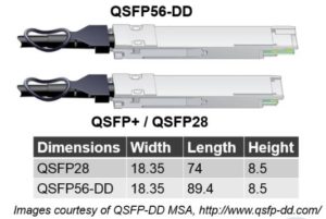
The form factor of an optic essentially defines the supported data transfer rate (speed) per lane, number of data transfer lanes, physical size and power characteristics of the optical transceiver.

Within each specific form factor there are multiple optical transceiver options which differ in the supported distance range and type of connectors and cabling they support.

You will see transceivers rated at specific distances when paired with a certain cabling type.  Some example distance designations that commonly appear are SR (short-reach), IR (intermediate-reach) or LR (long-reach) which when combined with a supported cabling type will range from as few as 100m on Multi-mode fiber (MMF) for SR to upwards of 10km on Single-Mode Fiber (SMF) in the case of LR.

When it comes to cable types, Multi-mode fiber (MMF) cable is used in the Data Center for distances less than 400m. Single-Mode Fiber (SMF) cable is used for distances >400m where the connected end device is across the Data Center or for much longer distances like interconnects between Data Centers (DCI) that may span multiple kilometers. Cat6 and Cat7 copper cabling is still used for very short distance 1G and 10G connections.

In the Data Center the transceiver’s connector type is typically either an LC connector or an MPO/MTP connector.  Duplex Single Mode Fiber (SMF) and Duplex Multi-Mode Fiber (MMF) cable types both support LC connectors while parrallel MMF trunks utilize MPO/MTP connectors. More on MPO/MTP below.  RJ45 copper connector types for use with Cat6/7 cabling are also possible with some transceivers.

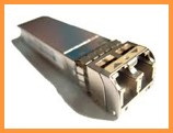
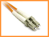
Figure 1: SFP transceiver (left) which accepts a cable with an LC connector (right)


MPO/MTP Connector

Multi-Fiber Push-On/Push-Off (MPO) is the standard and MTP is a brand of connector type. These connectors deal with handling the patching or termination of multiple parallel multi-mode fiber strands called ‘MTP trunks’. The most commonly seen type of parallel multi-mode fiber strand for interconnecting two devices is the 12-fiber MTP ‘trunk’ which consists of a length of 6-fiber pairs with MTP connectors on each end.  In practice only 8 of the 12 fibers are actually used which is enough to provide 4 lanes of dual fibers.  More efficient 8-fiber MTP trunks also now exist and are gaining in popularity.  These MTP connectors commonly plug into either a QSFP+ 40G or QSFP28 100G form factor optical transceiver which both use 4 parallel data transfer lanes and are used for short length connections of <400m.

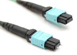
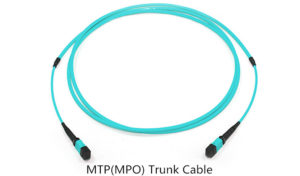
Figure 2: Male and Female (top) MTP connectors, MTP trunk Cable (bottom)


MTP harness connectors also exist which, for example, can take an 8-fiber MTP and break it out into 4xLC connectors. This would typically be used to breakout a 40G or 100G port on a switch to 4x10G or 4x25G endpoint connections respectively. This harness might plug directly into a switch port to breakout connections to a server in the same rack as the switch or used in conjunction with an in rack patch panel which provides connectivity to all the servers in rack.

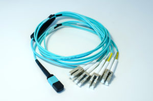
Figure 3: 8-fiber MTP to 4 LC duplex harness


There are also versions of transceivers that have a cable directly pre-attached to them and therefore have no real connector. These Direct Attach Copper (DAC) or Active Optical Cables (AOC) are for very short distance connections in the range of 1 to 30m and are described in more detail further below.

Direct Attach Copper (DAC)

This is essentially a cable with the 10G SFP+, 40G QSFP+ or 100G QSFP28 transceivers pre-attached on both ends.  These exist in either passive or active mode with passive having an effective distance of 1-5m while active can cover 5-10m of distance between the switch port and connected device. DAC is mostly used for in rack cabling when the switch and the connected device are in the same rack (Top-of-rack model). It is also possible to use an active DAC to extend the reach between a connected device to a middle of row or end of row switch location.
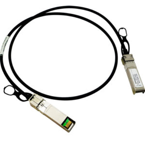
 Figure 4: DAC Cable


Direct Attach Copper Break-Out (DACBO)

This functons just like the DAC above with the key difference being that the switch port end of the DAC will be  have a 40G QSFP+ or 100G QSFP28 transceiver while the connected device end will have 4x10G SFP+ or 4x25G SFP28 connections available. These are typically used within a rack (TOR model).

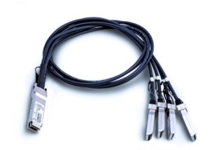
Figure 5:DAC Break-out Cable


Active Optical Cables (AOC)

AOC are just like DAC in that the transceivers and the cable are a single fixed assembly. The key differences here are AOC being fiber which is thinner and more flexible with much longer effective reach in the 10 to 30m range allowing for them to be used in conjunction with middle and end of row switching device location designs.  The drawback to using a really long AOC cable that runs from and end of row switch location to a device in a remote rack is that the entire cable assembly needs to be re-run in the event of a failure which may prove cumbersome. AOC’s also have breakout options for enabling 40G and 100G to breakout to 4x10G and 4x25G respectively. AOC’s are more expensive than DAC cables due to both active components and longer length cables.

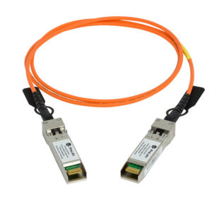
Figure 6:Active Optical Cable
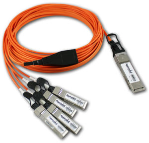
Figure 7: Active Optical Break-out Cable


Commonly used form factors

Next let’s look at the available type of optics form factors, how they have been historically used in DC switching gear as well as their performance, size, power and cost trend.

SFP+ – 10G Small Form Factor Pluggable Tranceivers

SFP+ is a single lane of 10Gbps which utilizes 1.5W of power.   SFP+ transceivers can support RJ45 copper, LC fiber connectors or Direct Attach Copper (DAC) and Active Optical Cables (AOC). Typical 1RU switch configurations which leverage SFP+ have 48 SFP+ ports with 4 to 6 ports of QSFP+ 40G or QSFP28 100G for uplinks.  10G Data Center switches produced with SFP+ ports are now starting to give way to 25G switches with SFP28 ports and QSFP28 uplinks.

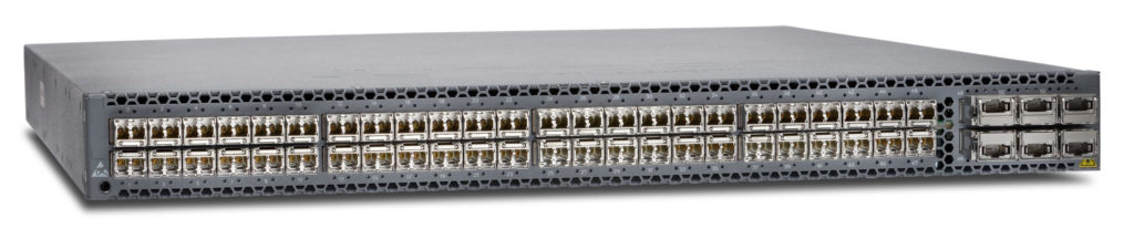
Figure 8:  Juniper QFX5100-48s 1RU 48x10G SFP+ and 6x40G QSFP+ uplink Broadcom Trident 2 based switch


QSFP+ – Quad 10G Small Form Factor Pluggable Tranceivers

The QSFP+ is 4 lanes of 10Gbps which is slightly wider than an SFP+ and utilizes 3.5W of power.  When comparted to SFP+ its 4x the bandwidth at roughtly 2.5x the amount of power consumed.  QSFP+ transceivers will support LC fiber connectors, MPO/MTP connectors, Direct Attach Copper (DAC) and Active Optical Cables (AOC).  It’s common to see 32 ports of QSFP+ on a 1RU ethernet switch and 36 QSFP+ ports on a modular chassis line card as this is typically the maximum amount of front panel real estate available for ports.

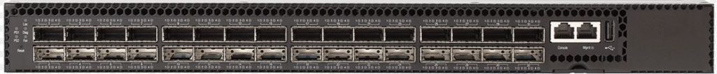
Figure 9: EdgeCore 1RU 32x40G QSFP+ Broadcom Trident 2 based switch


SFP28 – 25G Small Form Factor Pluggable Tranceivers

The SFP28 is a single lane of 28Gbits which is 25Gbps + error correction for an effective data rate of 25Gbps.  SFP28 is the same size form factor as SFP+ so its 2.5 times the bandwidth of SFP+ in the same amount of space and at roughly the same price point.  In addition, SFP28 is also backwards compatible with 10GE which allows for upgrading the DC switching infrastrucuture to support 25G without immediately having to also upgrade all of the devices that will plug into it _and_ allows for reuse of existing 2-pair MMF cabling.  1RU switching products have been introduced with 48x25G SFP28 densities with 4-6 additional ports supporting QSFP28 used as 100G uplinks.

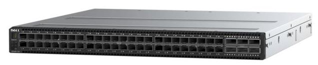
Figure 10: DEll S5148F-ON 1RU 48x25G SFP28 and 6x100G QSFP28 uplink Cavium Xpliant based switch


QSFP28 –  Quad 25G Small Form Factor Pluggable Tranceivers

The QSFP28 is 4 lanes of 28Gbits (25Gbps + error correction) providing either full 100Gbps operation or a break-out of (4) 25Gbps interfaces.  Its important to note that the QSFP28 is the same size form factor and power draw as the QSFP+, yet provides 2.5x time bandwidth of QSFP+.  Due to the same size form factor its possible to see switching equipment flexibly support the use of either QSFP+ or QSFP28 pluggable optics in the same port(s).  Most 1RU switches will have 32xQSFP28 ports which will support break out QSFP28 to 4x25G. Modular switch chassis will sport line cards that leverage between 32 and 36 ports supporting QSFP28.  QSFP28 is also popular as a 100G uplink port in newer 48x25G 1RU switches.

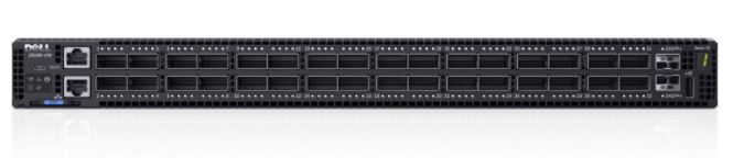
Figure 11:  Dell Z9100-ON 1RU Broadcom Tomahawk based switch with 32x100G QSFP28 ports


Device placement in the Data Center

Another key concept to understand is the typical switch device placement locations in the Data Center

Top-of-Rack (TOR) Designs


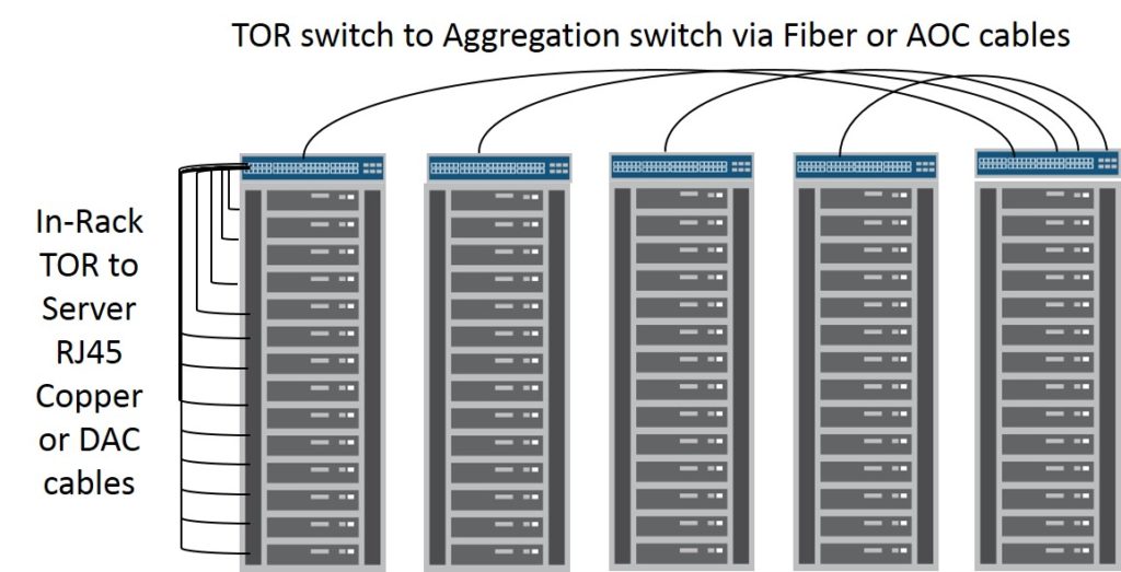
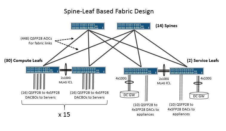
Top-of-rack or TOR model consists of placing a switch within the same rack as the devices which are connecting to it.  The switch might be placed in the top most portion of the rack or in the middle of the rack with 1/2 the servers above it and the other 1/2 below it.  In this case its common to see either RJ45 copper or DAC cables use to connect in-rack devices to the switch due to the very short intra-rack cabling distance requirement.  This short intra-rack wiring scheme also obviates the need for additional space and cost of patch panels for the rack. The only connections that leave the rack should be uplinks from the TOR switch to middle-of-row or end-of-row spine or aggregation switches which typically would be fiber or even AOC based. From a maintenance or failure domain perspective we are dealing with isolation to the rack level so only devices within the rack will be impacted.

Due to the high front panel density counts on 1RU switches deploying a pair of switches in each rack for redundant server connectivity potentially strands a lot of excess ports on each switch.  For example if you have a desire to multi-home your servers to a pair of 48-port switches, yet only have 24 servers per rack you could x-connect your servers to another 48-port TOR switch in an adjacent rack. While this reduces the total number of switches and leaves no unused ports it makes for slightly more cumbersome x-rack cabling.

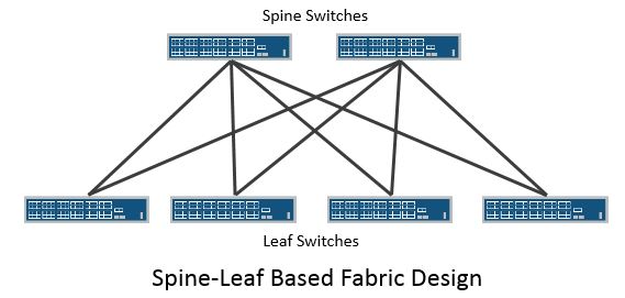
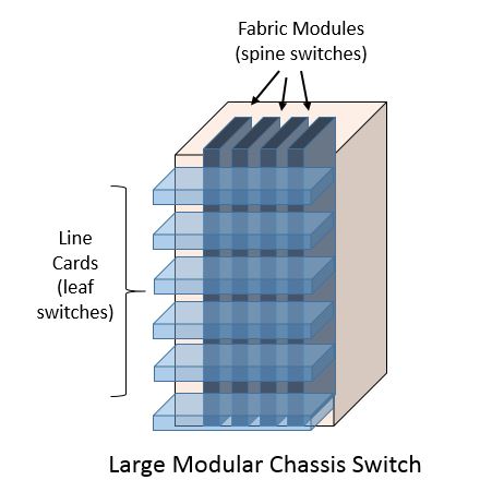
Middle-of-Row or End-of-Row Designs

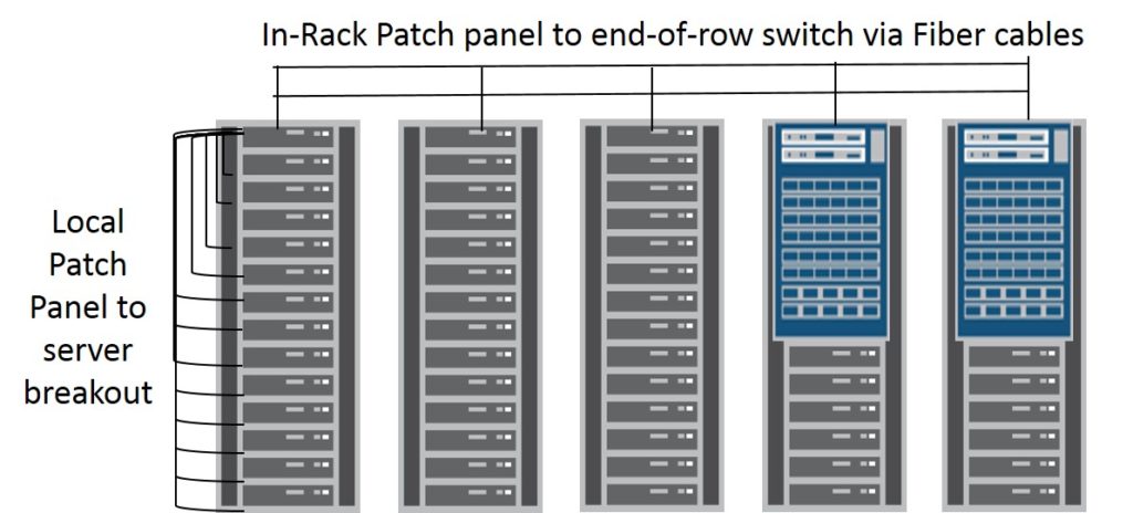
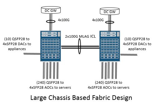
Middle-of-row and End-of-row designs typically consist of a pair of large chassis based switches that aggregate the server connections from all of the racks/cabinets that are in the row.  In this model there is no switching device within the rack itself. The connections between the large chassis based switches and each rack would typically be fiber runs that terminate onto in-rack patch panels.  From the patch panel individual patch cables would be run to each server in the rack. It is technically possible to run cables the full length of the distance between the middle-of-row or end-of-row chassis based switch pair, however when a cable fault occurs the entire length of the run needs to be replaced which could be cumbersome to deal with.

From a maintenance or failure domain perspective we are dealing with the potential to impact multiple racks in the event of a large chassis based switch failure.


Lets conclude by putting it all together with a table that illustrates how the various form factor, transceiver, connector and cable types combine to offer choices in the placement of the end devices connected to Data Center switches.

Commonly used 10/25/40/100G Data Center Connectivity Options

Media Form Factor Cabling and ConnectorType Max Distance Type of connection
10GBase-T (Copper) SFP+ CAT6/CAT7 100m server/appliance within the same rack (10G TOR switch)
10G-USR (Fiber) SFP+ duplex MMF w/LC connector 100m server/appliance within the same rack (10G TOR switch)
10GBase-SR (Fiber) SFP+ duplex MMF w/LC connector 400m server/appliance within the same rack (10G TOR switch) or to chassis based switch in end of row (EOR)
10GBase-LR (Fiber) SFP+ duplex SMF w/LC connector 10km device is cross-DC, between floors, external to DC/DCI
SFP+ Direct Attach Copper 1 to 5m server/appliance within the same rack  (10G TOR switch)
SFP+ Active Optical Cable 5 to 30m server/appliance within the same rack (10G TOR switch) or to chassis based switch in end of row (EOR)
25GBase-SR SFP28 duplex MMF w/LC connector 100m server/appliance within the same rack (25G TOR switch)
SFP28 Direct Attach Copper 1 to 5m server/appliance within the same rack (25G TOR switch)
SFP28 Active Optical Cable 5 to 30m server/appliance within the same rack (25G TOR switch) or to 25G chassis based switch in end of row (EOR)
40GBase-SR4 (Fiber) QSFP+ 12-fiber MMF w/MPO connector 150m server/appliance within the same rack (40G TOR) or to chassis based switch in end of row (EOR)
40Gx10G-ESR4 (Fiber) QSFP+ 12-fiber MMF w/MPO connector 400m server/appliance within the same rack (40G TOR) or to chassis based switch in end of row (EOR)
 40GBASE-CR4 QSFP+ Direct Attach Copper 1 to 5m server/appliance within the same rack or 40G leaf to 40G spine switch
QSFP+ Active Optical Cable 5 to 30m 40G leaf to 40G spine switch or to 40G chassis based switch in end of row (EOR)
QSFP+ QSFP+ to 4xSFP+ DACBO 1 to 5m 10G server/appliance within the same rack
QSFP+ QSFP+ to 4xSFP+ AOC 5 to 30m 10G server/appliance within the same rack (40G TOR) or to chassis based switch in end of row (EOR)
100GBase-SR4 (Fiber) QSFP28 12-fiber MMF w/MPO connector 100m server/appliance within the same rack (TOR)
100GBase-LR4 (Fiber) QSFP28 duplex SMF w/LC connector 10km device is cross-DC, between floors, external to DC/DCI
 100GBASE-CR4 QSFP28 Direct Attach Copper 1 to 5m server/appliance within the same rack, device to device 100G connectivity (100G leaf to 100G spine)
QSFP28 Active Optical Cable 5 to 30m device to device 100G connectivity (100G leaf to 100G spine switch) or 100G chassis based switch in end of row (EOR)
QSFP28 QSFP28 to 4xSFP28 DACBO 1 to 5m 25G  server/appliance within the same rack (100G TOR)
QSFP28 QSFP28 to 4xSFP28 AOC 5 to 30m 25G  server/appliance to 100G chassis based switch in end of row

I hope you found this useful and now have a better understanding of how to use these components to construct a Data Center cabling scheme.


Disclaimer: The views expressed here are my own and do not necessarily reflect the views of my employer Juniper Networks

Spine-leaf versus large chassis switch fabric designs

With every mega scale web company talking about their spine-leaf fabric designs it sounds as if everyone who is building a Data Center switch fabric needs and is going to implement one.  Is that really the case though?

In this blog post we will look at whether spine-leaf designs are always better than large chassis based Data Center switch fabric designs. We will touch on some important factors to consider when choosing between which fabric design to implement.  Next I will provide a simple example for comparison that will better illustrate why several of these factors are critically important.

First off let’s start with what a spine-leaf fabric actually is.  It’s a physical topology design where endpoints connect to leaf switches and all leaf switches connect to a spine switch layer. Every leaf connects via an uplink port to each of the spines. The spines don’t connect to each other, just to the leaf switches. This physical topology design results in every endpoint being an equidistant number of hops away from every other endpoint with consistent latency.  There are effectively 3 stages in this design where there is an ingress leaf stage a middle stage via the spine and an egress leaf stage. This design is sometimes referred to as a Clos fabric, after Charles Clos who created this design back in 1952 in order to scale a network larger than the radix of the largest telephone switch that was available at the time.  This design being rooted in the need to scale past the largest available switching component will be a key factor we consider later in this post when comparing a large chassis based design to a spine-leaf design.  A spine-leaf topology can be utilized for a layer 2 or a layer 3 fabric.  It is most often coupled with an L3 design, commonly referred to as an ‘IP Fabric’, where routing is employed on all of the interconnection links between the leaf and spine switches. Every endpoint connected to a leaf switch is reachable via N # of equidistant ECMP paths where N is the # of spine switches in use.  In the layer 3 “IP Fabric” paradigm the result is effectively a distributed control plane.

In contrast a large modern chassis based switch is actually a Clos fabric enclosed in a single piece of sheet metal with a shared control plane, power and cooling subsystem. The line cards act like leaf switches and the fabric modules act like spine switches. The fabric links that interconnect all of the line cards (leafs) are internal to the switch fabric modules (spine) and don’t require a conventional routing protocol between them as there is a single control plane in the chassis based system which updates the forwarding tables on the line cards.

Note:  Its worth mentioning that there is technically a hybrid model of the single control plane chassis based switch and the distributed control plane spine-leaf fabric.  An Open Compute Platform (OCP) design called “Backpack”, submitted by Facebook, now exists for a 4-slot chassis comprised of 32x100GE line cards and integrated fabric modules. The difference in this design is that each component inside the shared chassis is a separate switch from a control plane and management plane standpoint. This basically acts like a Clos fabric in a box whereby the fabric cards act as discrete spine switches and the line cards act as discrete leaf switches running routing protocols between each other.  So while the packaging looks like an integrated modular chassis design its really comprised of a dozen individually managed components.  Facebook is actually using tens (if not hundreds) of these 4-slot chassis together as a building block in a massive spine-leaf fabric design. This means lots of individual devices to manage and monitor.  The major benefit to this approach is improved cable management as fabric interconnects between spine and leaf are internal to the 4-slot chassis as well as better cooling.

Now that we have a better understanding of what a spine-leaf fabric is let’s look at the big picture view. What are the actual business requirements that you are building a Data Center network towards? Are you building your network according to the requirements of an application that you are developing or are you building it to run “anything” that might get thrown at it? The former is the case when you look at companies like Facebook or LinkedIn that seek to make the network technology interface with the business better. The latter occurs when you are building an Infrastructure as a Service (IaaS) Data Center fabric that will host someone else’s applications.  Is the application designed with scale out and fault tolerance built in, or is it expected that the network will deliver this on its behalf? You need to know the requirements and behavior of the application. Is ultra-low latency required? Is packet loss tolerated? Is every end host consistently using all of its available bandwidth or is the traffic pattern less deterministic?

How big does your Data Center fabric need to be? Don’t just assume that you need to do a spine-leaf design because that’s what all the massive scale players are doing.  The key here is ‘massive scale’. These companies have unique problems to solve at the largest known scale in the industry.  You need to be realistic here and ask yourself is your Data Center network actually going to need to scale as large as a Google, Facebook or LinkedIn? If you are only talking about 2,000 servers versus 20,000 to upwards of 100,000 then you are building a very different network then the massive scale players in the industry.

What tech is in your network team’s wheelhouse? Are they comfortable with a routing protocol like BGP and proficient with configuration automation and telemetry collection tools required to deploy and monitor a very large scale Data Center fabric compromised of tens if not hundreds of individual network devices?

Another interesting concern is whether or not you intend to pursue a disaggregated software and hardware strategy whereby the switch Network OS (NOS) and the switch HW come from different vendors as opposed to the traditional ‘vertically integrated’ model of SW and HW coming from the same vendor.  This is important to know up front as there currently appears to be far less options for switch NOS’s that will run a large chassis based switch versus the smaller 1 or 2RU Top-of-Rack (TOR) switches.  At the time of this writing the only OCP submitted designs for a large chassis based switch are the Edgecore Networks OMP 256 and 512 models. What this inevitably means is that a 1/2RU open networking switch will give you much a greater choice of Switch NOS and Switch Hardware options.

If you decide to go with a large chassis based switch from a traditional ‘vertically integrated’ network vendor you are likely going to stay with that network vendor for 5-7 years and upgrade the line cards in the switch chassis to go to the next highest interface speed and density cards when needed. With the spine-leaf design everything is a distributed line card and you replace the individual switches with another switching silicon generation of 1RU switches when needed. At this point, given the broader choices in the open ecosystem in the smaller 1 or 2RU fixed switches space, you can elect to change out the hardware or software vendor.

 Consideration Large Chassis Switch Pair Spine-Leaf “IP Fabric”
Fabric Construct Fabric links between line cards are internal to the chassis. Usually proprietary, hard to debug w/out vendor TAC, hard to see what is really going on Fabric is composed of external links between switches running standards based protocols. Easy to monitor and understand what’s happening on the links using a well-established troubleshooting methodology.
Failure Domain Large fault domain here. Losing an entire switch means losing ½ your fabric bandwidth. For SW upgrades you really need mechanisms like NSR and ISSU to work reliably else you will have long reboot times. Small failure domain. Individual switches can fail or be upgraded separately to reduce impact. Shorter reboot times as we are dealing with individual switches
Rack Units (RU) and power Chassis based switches will consume some extra rack units and power for routing engines and other shared system components. How many rack units and power consumed will largely depend on how much oversubscription is acceptable for your application as increasing fabric bandwidth involves adding more spine switches (which means more optics and cabling as well)
Optics/Cabling Chassis design will use less optics and cabling due to the fabric interconnection links being internal to the chassis S/L requires optics and cables for constructing the external fabric interconnections between switches
Config Management Only 2 devices to manage as long as we are building to less than 2,000 server facing ports 10’s of devices to manage. Need to implement a config automation tool/process. Uses more IP addresses for P2P links between switches. Needs a routing protocol configured as the distributed control plane of the fabric
Oversubscription In a typical chassis based switch there should be no oversubscription The acceptable level of oversubscription is key to number of overall spine switches, fabric links, optics/cables, IP addresses, rack units and power
Packet Buffers Custom ASIC based chassis switches typically have deep buffers (GB), though there are some that leverage merchant silicon with shallow buffers (MB). 1 and 2RU merchant silicon switches typically come with shallow buffers (MB) though there are some exceptions here as well

Let’s take a look at how some of these factors listed above combine to play out in a simplified example.  In this case I’m simply going to determine the maximum amount of dual-homed servers with 25G NICs that can be supported in a large chassis based system and then attempt to build a spine-leaf fabric design with the same level of reach and oversubscription.  For this example I’ve decided to compare a large 8-slot chassis fabric based on Broadcom Tomahawk merchant silicon with a spine-leaf fabric of 1RU switches based on the same merchant silicon switching ASIC to make this as much of an ‘apples to apples’ comparison as possible since each 1RU switch is equivalent to a line card or fabric module in the chassis based system. I’ve reserved a reasonable amount of ports in each fabric design to account for exit links towards the DC Edge Routers and some physical appliances like Firewalls, anti-DDOS, Monitoring Probes and other devices that may need to exist in the Data Center. The legacy hosted applications in this DC are not distributed fault-tolerant applications and therefore will require active/active 25G LAG connections to the switches for providing higher availability.


Consideration Large Chassis Switch Pair Spine-Leaf “IP Fabric”
Switch Hardware (2) 8-slot chassis w/32x100G line cards (46) Total 1RU 32x100G switches

•(30) 1RU compute leafs

•(2) 1RU service leafs (host DC GW/PNFs

•(14) 1RU spine switches

Total Rack Units 26RU 46RU
Total (Max) Power 12KW 17.5KW
Hardware location Middle-of-row (MOR) in network cabinet Leaf in Top-of-Rack (TOR) in server cabinets and MOR network cabinet for spine switches
Number of dual-homed 25G servers 960 (30 server racks of 32 servers) 960 (30 server racks of 32 servers)
Oversubscription None ~1.2:1
Total non-server ports (to DC GW/MLAG ICLs/Appliances/Free ports) 8x100G/4x100G/10x100G/0 8x100G/64x100G/10x100G/18x100G
Cabling


This example utilized combinations of Active Optical Cables (AOC), Direct Attach Copper (DAC) and Direct Attach Copper Break Out Cables (DACBO)

(480) QSFP28 to 4xSFP28 AOCs to the servers

(480) + (8 to DC GW + 2 DACs for MLAG Inter-Chassis-Links (ICLs) + 10x QSFP28 to 4xSFP28 DAC for Appliances) = 500 physical cables

(448) QSFP28 AOCs from middle of row spines to leafs in the top of rack

Leaf to servers via (16) QSFP28 to 4xSFP28 DACBO per leaf per rack

(448) for 100GE fabric links + (16) QSFP28 to 4xSFP28 DACBO per leaf to the servers x 30 racks = 928 + (8 to DC GW + 32 DACs for MLAG ICLs +10 for appliances) = 978 physical cables

Optics 8 to DC GW = 8 (100G QSFP28 SR4)

* QSFP28 to 4xSFP28 AOC and DAC cables means no 25G optics on the servers, appliances or MLAG ICLs

8 to DC GW = 8 (100G QSFP28 SR4)

* QSFP28 DAC and QSFP28 to 4xSFP28 DACBO means no 25G optics on the servers, appliances or MLAG ICLs

Total addressable links (IPv4 addresses) 30 IRBs + 2 for MLAG ICL + 2 for LAGs to DC GW + 40 for PNFs = 74 896 (p2p fabric links) + 32 for MLAG ICLs  + 2 for LAGs to DC GW + 40 for PNFs =  970

There are some interesting observations that can quickly be made here.

  • First to get to nearly the same level of oversubscription with the spine-leaf fabric design I need to consume 20 more Rack Units and 5.5 KW more power. Most of this is attributable to the need to have physical links between the spine and leaf switches which consume (16) 100GE ports on the leaf switches that are not required to be used on the line cards inside of a chassis based switch as those connections are internal to the switch fabric in the chassis. The ‘external switch fabric’ of the spine-leaf design requires (14) rack units worth of spine switches to deliver the same function as the fabric modules which are internal to the chassis based system.
  • The requirement to dual-home the 25G NICs on the servers to a pair of switches via LAG requires burning 2 additional interfaces between each pair of leaf switches for running the MLAG/MC-LAG inter-chassis links. In the chassis based switch this only requires a single pair of links for running the MLAG/MC-LAG ICL between the two chassis.  Also important to note here is that MLAG/MC-LAG only works between a pair of switches.  So when you connect the servers directly to a pair of large chassis based switches you have already confined the limit of how big the fabric can be to 2 switches.
  • The total number of IP addressing required to build the spine-leaf design is significantly higher primarily due to the need to address all of the P2P links that comprise the physical fabric links between the leaf and spine switches.

Another interesting observation was that the choice of location of the switches and the type of cabling in use can make a huge difference in the amount of cables and type and cost of the optics required. There are several different permutations here that could have been chosen and the decision tree for where to place the switches and how to run the cabling warrants its own blog post.  The use of Direct Attach Copper (DAC), Active Optical cables (AOC) and Direct Attach Copper Break-Out (DACBO) cables created a large reduction in the 100G optics required.  I think it’s safe to say that an optimum rack placement and cabling solution can be found for either the chassis based fabric design or spine-leaf fabric design, such that neither fabric design solution should have a tremendous advantage or disadvantage here.


Conclusion:

If you can handle having a potentially very large failure domain, then a traditional large chassis based system can be a convenient option for deploying a non-blocking switch fabric POD of less than 2,000 ports (1,000 dual-homed servers).  It requires less devices to provide configuration management and monitoring for, less physical cabling, doesn’t need a routing protocol running between elements to bootstrap the fabric and consumes less IP addressing.

However, if one intends to extend the Data Center fabric to 3 to 5 times this size then N more large chassis based systems would need to be deployed. What is also needed is another layer of chassis based switches introduced for interconnection between all of the PODs which would constitute a spine layer. What you now end up with in that case is a spine-leaf fabric constructed entirely of chassis based switches. The failure domain in this scenario now becomes incredibly important.  If the spine layer that interconnects all of these PODs is a pair of 100G chassis based switches you can lose a large portion of bandwidth between any 2 PODs in your Data Center. The configuration management and monitoring advantages of the large chassis based system model also goes away in a Data Center of this size.


Disclaimer: The views expressed here are my own and do not necessarily reflect the views of my employer Juniper Networks